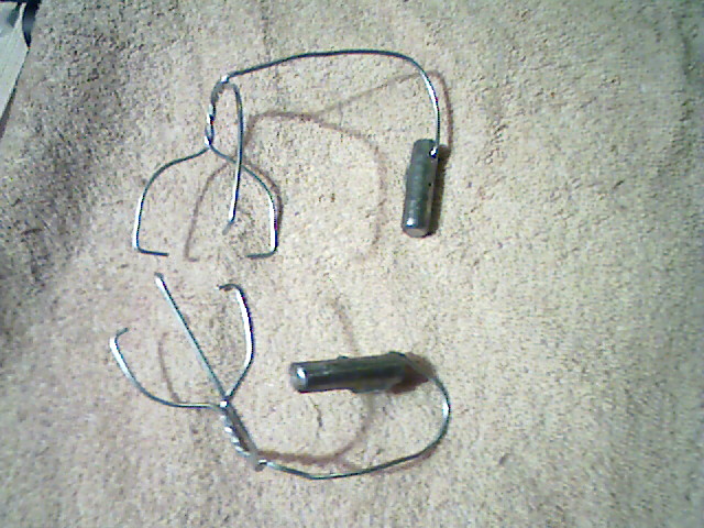
Here are the Rear Wheel Bias Assemblies ready to be attached to a PW car for rear whell alignment.
This "three-point hitch" style of Weight Assembly is suggested for use with one's own cars. Further, three separate assemblies with nearly identical weight are suggested to minimize the problems of getting the weight oriented for specific uses. The cases are left rear bias, right rear bias, and front wheel bias.

Here are the Rear Wheel Bias Assemblies ready to be attached to a PW car for rear whell alignment.
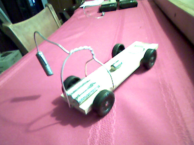
This weight attaches so that the left rear wheel carries more weight and the right rear wheel carries less weight. The weight on the front wheel(s) should not change.
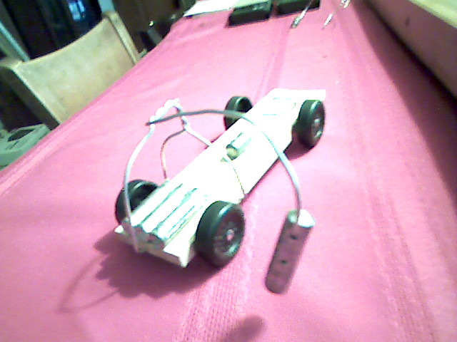
This weight attaches so that the right rear wheel carries more weight and the left rear wheel carries less weight. The weight on the front wheel(s) should not change.
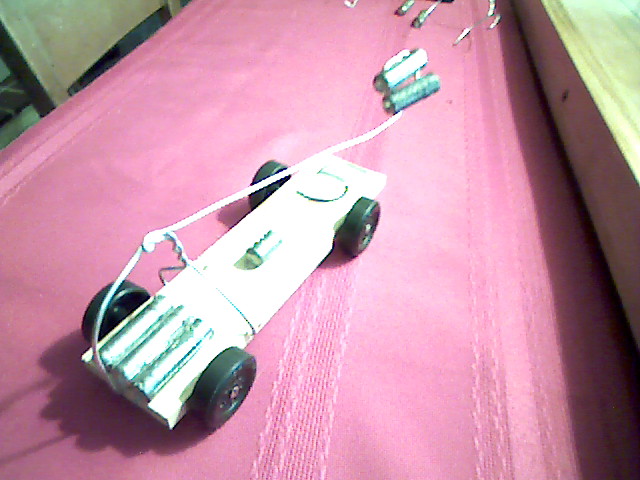
This weight attaches so that the front wheel(s) carry more weight and the rear wheels load is unchanged.
The wire is 16 gage steel wire sold for joining rebar. The important characteristics are strength, resilience, weight, and flexibility. The wire must be flexible enough that the location of the lead slug can be adjusted in small increments relative to the three "hooks" that attach to the car. So, "spring steel" would be very frustrating to adjust! I start with two wires, 8" and 12" long respectively.
The holes drilled in the sides of the car are done with a drill approximately the size of a #44 and are about 1/16" deep.
My current generation of Weight Assemblies weigh 1.15 onces each and are constructed using lead slugs of approximately 0.9 ounces. The "arm" holding the lead slug must reach out approximately 4 inches from the center of the car. More reach is needed for the "long arm" weight used for biasing the dominant front wheel when analyzing differential rear friction.
You may, of course, develop your own weight assemblies. You may invent something that works much better for you.
The important aspect of the weight assemblies is the ability to transfer weight from one wheel to another. This means that the assembly must be able to lift as well as depress.
| Launch in external player |
I initially tried an exact implementation of the cantilever concept by forming the assembly with two "hooks" and a center "post". The picture below shows the hooks attached under the side and rear of the car and the post resting on top of the car.
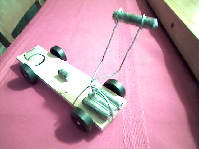
An early design.
This arrangement was stable enough, but I found it difficult to switch this type of bias weight quickly from left side to right side because there was no indexing of the hook locations. At that stage of the process development, I was unsure how critical the fore-aft location of the added weight would be. The weight on the front wheel(s) varied widely depending on just where the hooks were located. So I abandoned this design in favor of the "three-point hitch" design shown at the top of this article.